Overview
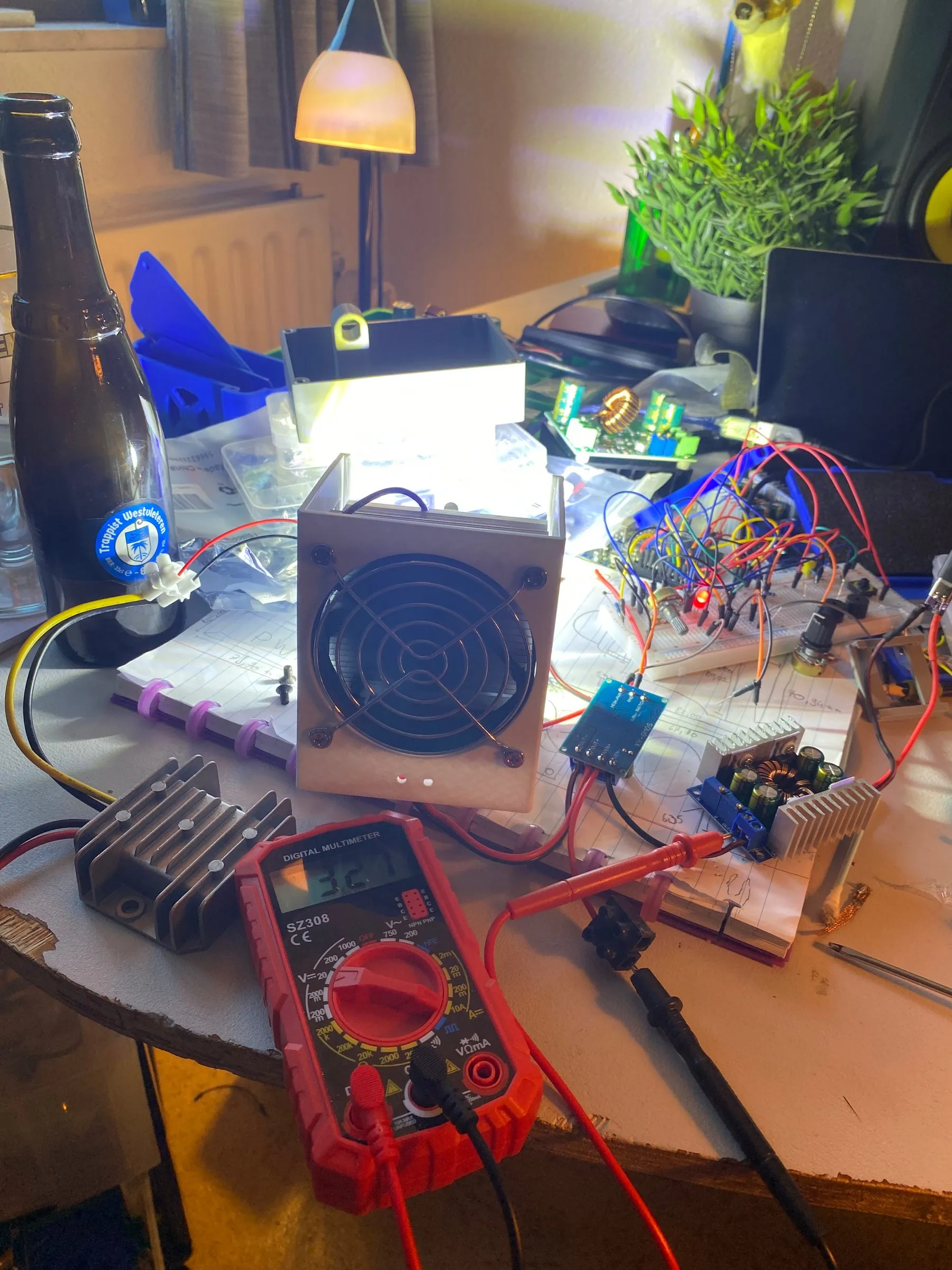
A 50W COB LED work light that draws all its power over USB-C Power Delivery, including straight from my eBike powerpack, or any PD adapter capable of delivering 50W. Started on 2 June 2026 with the Arduino circuitry, the goal was less “I need a light” and more “how much can I learn building one”: PD power negotiation, buck-boost conversion, PWM dimming, embedded safety logic, and a fully custom 3D-printed enclosure.
The result is a light that not only dims and displays live stats, but actively protects itself and the power adapter feeding it, throttling output if the LED gets too hot or if the USB-C source can’t keep up with demand.
Key features
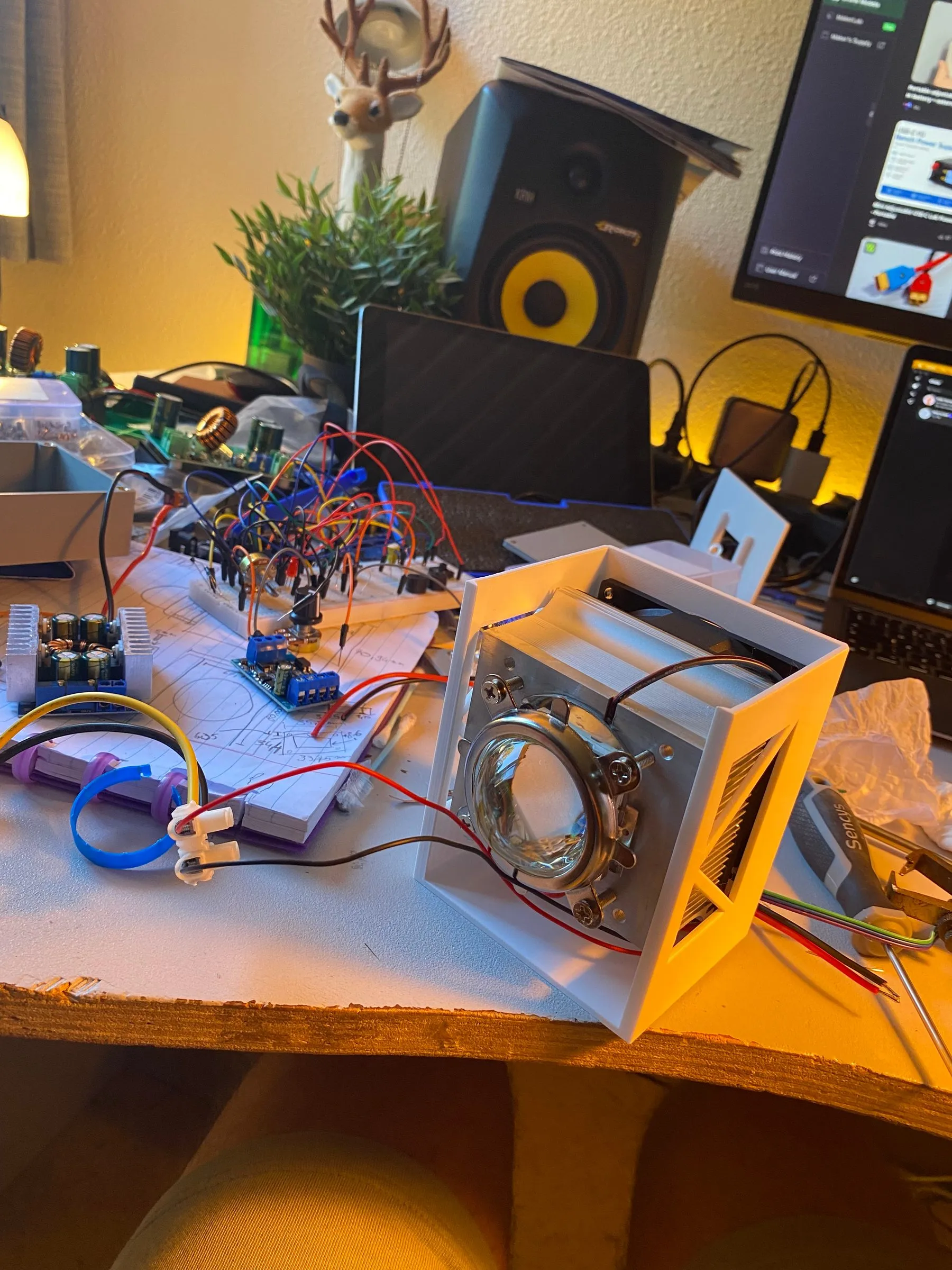
- 50W COB LED driven from a USB-C PD trigger board requesting 20V, stepped through a buck-boost converter to a regulated 15V with a 3.3A current limit, needed because the LED’s resistance drops as it heats up, so without a limit it would pull more and more current until it burned out
- Arduino Nano (chosen for its small form factor) controls brightness via a dedicated PWM regulator, adjustable through an onboard potentiometer
- Onboard display shows live stats: output percentage, input voltage, and calculated wattage/amperage draw to the LED
- Input voltage monitoring via a voltage divider, so the light won’t power on below 12V and can detect voltage sag (when the USB-C adapter can’t supply what the LED is demanding), automatically throttling output to bring the voltage back to normal
- Thermal protection: a thermistor mounted directly under the LED die tracks temperature. Output is throttled as it approaches 50°C, and the LED fully shuts off into a cooldown mode above that threshold, only turning back on once it’s dropped below a configured temperature
- Single-button interface to cycle which stat is shown on the display
- Active cooling: heatsink + thermal paste + 12V fan (with its own 12V converter, since nothing else in the system ran on 12V)
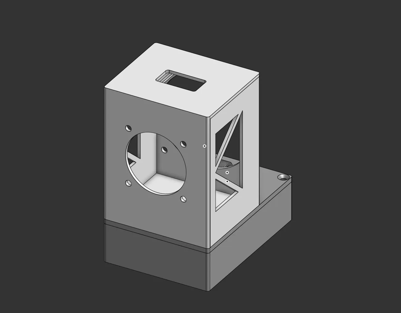
- Custom 3D-printed PETG housing (chosen for its heat resistance), split into two hinged halves (electronics base and LED head) so the beam angle can be adjusted and held at any tightness via the hinge
- Housing design details: flush countersunk screw holes and heat-set threaded inserts for mounting the lid and internal components like the buck-boost converter
Challenges
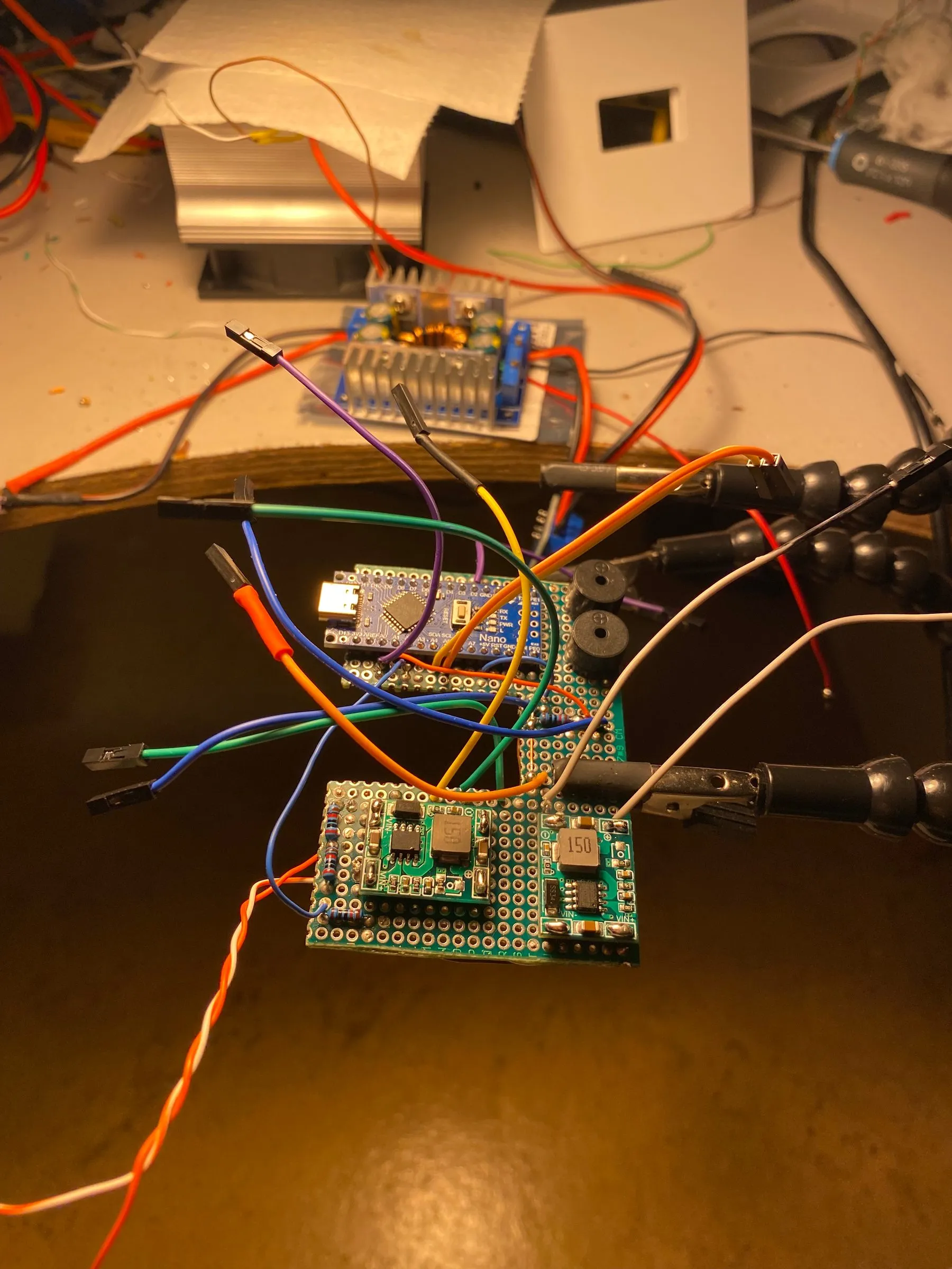
The biggest lessons came from buying the wrong parts before understanding the physics involved:
- First attempt used a fixed 12V buck converter with no current limiting. Turned out the LED needed 15V to hit its full potential, and more importantly, as COB LEDs heat up their resistance drops, so they pull increasing current at a fixed voltage. Without a current limiter, that’s a direct path to burning out the LED.
- For dimming, I originally used a motor PWM driver, which actually worked fine for the LED. But once I decided the Arduino should own dimming (to layer in the safety features), I tried to “hack” into the motor driver’s potentiometer input using optoresistors. It wasn’t reliable enough, so I switched to a dedicated PWM regulator that accepts a direct PWM signal from the Arduino.
- Getting the power output ramp curve right so the USB-C PD adapter doesn’t trip its own overcurrent protection when the LED suddenly demands a lot of current.
What I learned
- USB-C PD triggering and negotiating higher voltages for power-hungry loads
- Buck-boost conversion and current limiting as protection against thermal runaway in high-power LEDs
- Safely reading higher voltages into a microcontroller using a voltage divider
- Building real-time protection logic: voltage-sag detection and thermal throttling/cutoff with cooldown hysteresis
- 3D design techniques for functional enclosures, including heat-set insert holes, flush countersunk screws, and adjustable hinge mechanisms
- Iterating on hardware choices quickly when a component doesn’t actually meet the electrical or thermal requirements of the project